Wrecking the RPi Zero 2W, with E-Paper and bad soldering
Playing around with RPi Zero 2w, and an waveshare 2.13 e-Paper.
Besides my usual work talking about agile, working on products, having discussions on IT-related problems. Sometimes I also like to play around with some hardware. In 2012 I build an automated music player based on the lighting off the toilet. This was the last time I played with hardware and soldering.
 Arno van Rossum
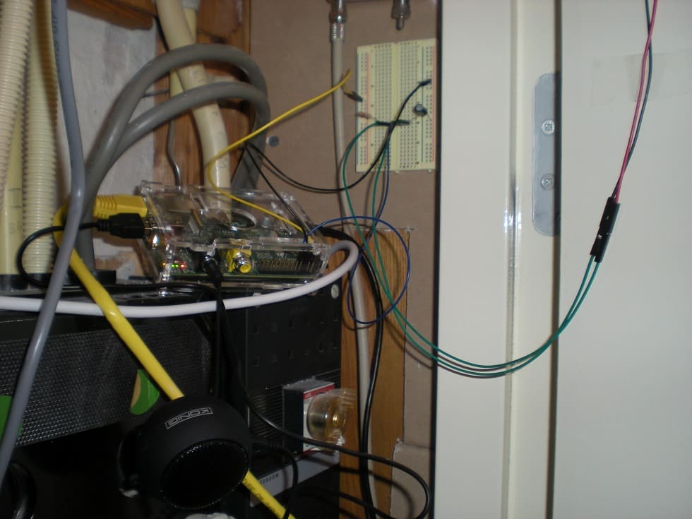
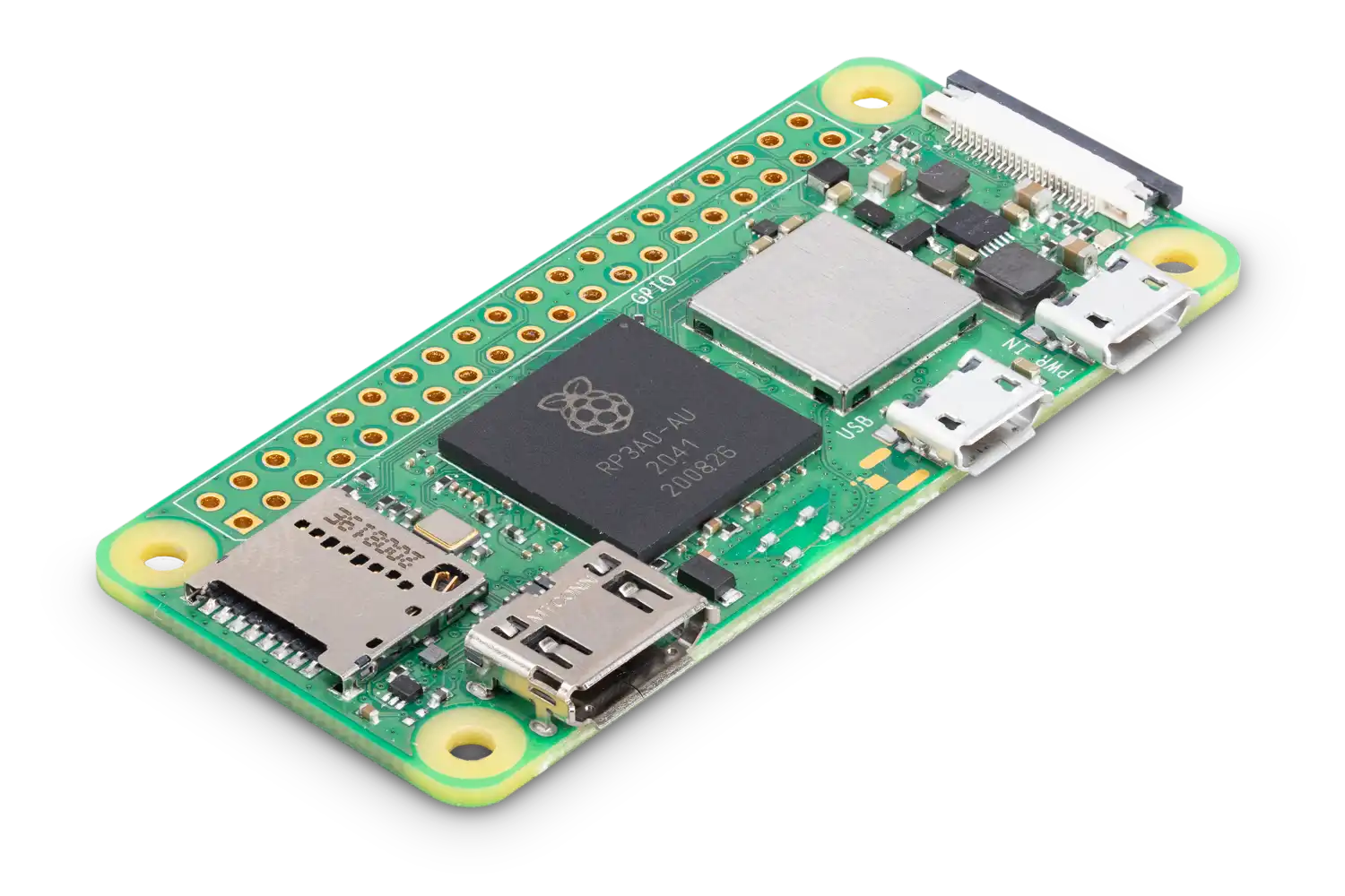
In this case, I bought some hardware:
 Raspberry Pi Ltd


I never played around with E-ink screens, so I thought why not give it a go, it's fairly cheap and accessible.
Plug that header
My journey began by simply adding the header to the zero 2W. Guess what, that didn't do anything, so I must dust off my soldering iron.
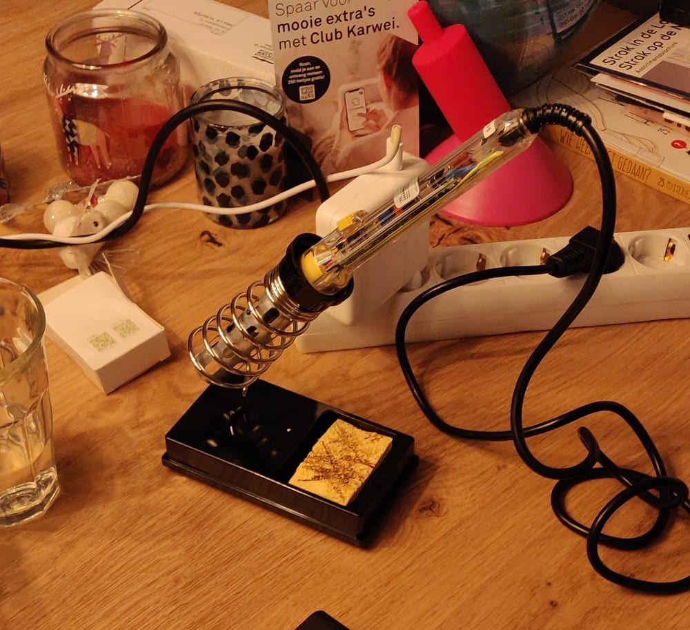
I didn’t touch it for at least 10 years, so I hoped it still worked. Eventually, I spent a whole evening trying to get the soldering on it, as the tip didn’t get enough heat to melt the tin properly. The side of the tip melted gradually. I had to keep the soldering iron for around 30 seconds on the tin to meld. Because I didn’t want to stop, I just continued, eventually getting all pins soldered.
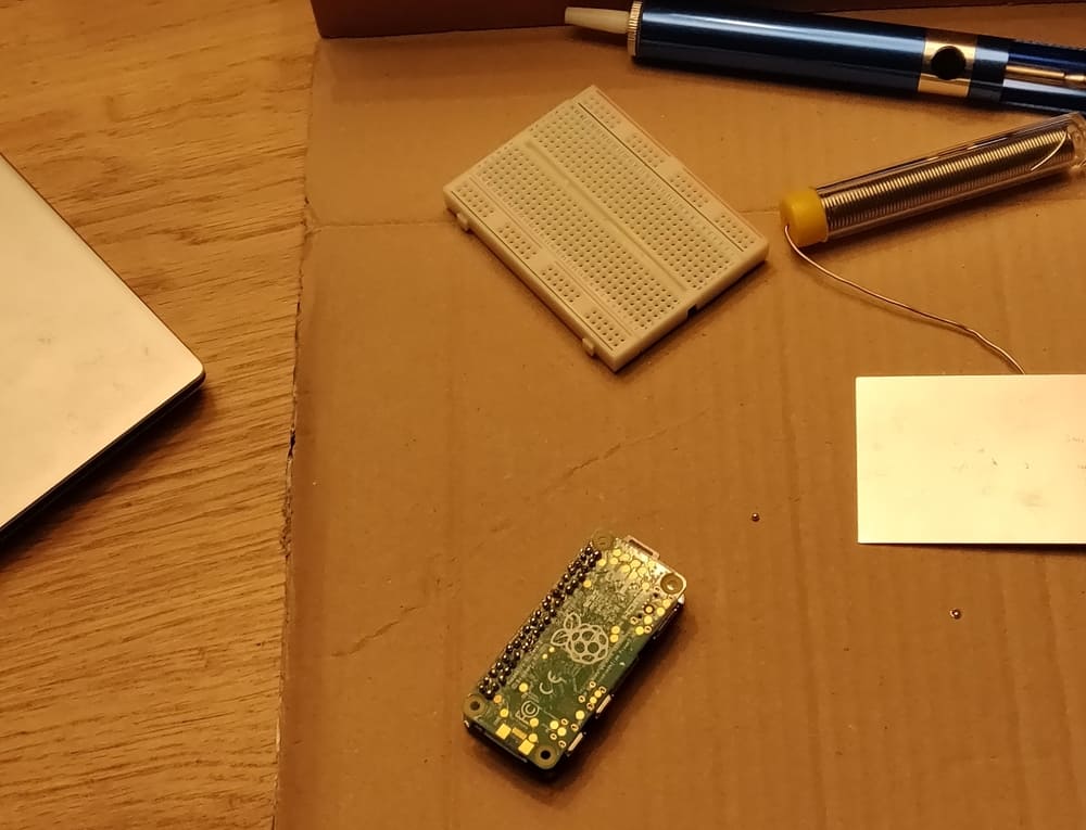
Well, I got the tin on, but it was definitely bad work! I played around for a few hours to get the E-ink to work, and I never got anything on the screen. Of course, I expected my bad solder work, and luckily I still had the first Raspberry Pi Model B at home, the 2012 variant with 26 headers. I connected the E-ink to the old raspberry and see if I get anything out of it.
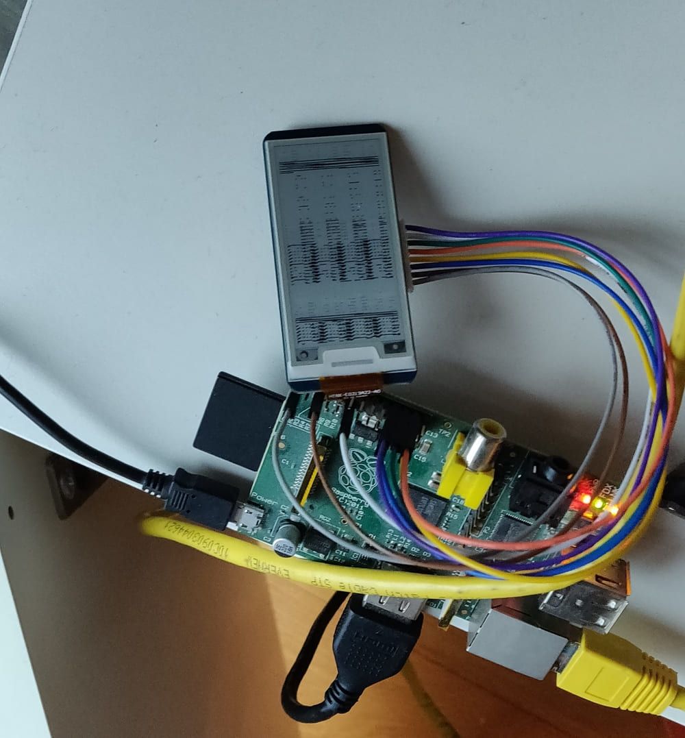
Not a pretty result, but it does something! At least I confirmed the E-ink screen is working.
Testing GPIO
The next step is checking if the soldering is correct. Thankfully there are 2 options. gpiotest from pigpio, and pintest from WiringPI. I tried them both:
pi@raspberrypi:~/pigpio-master/EXAMPLES/Shell/GPIOTEST $ sudo ./gpiotest
This program checks the Pi's (user) gpios.

The program reads and writes all the gpios.  Make sure NOTHING
is connected to the gpios during this test.

The program uses the pigpio daemon which must be running.

To start the daemon use the command sudo pigpiod.

Press the ENTER key to continue or ctrl-C to abort...

Testing...
Write 0 to gpio 24 failed.
Pull down on gpio 24 failed.
Write 0 to gpio 25 failed.
Pull down on gpio 25 failed.
Skipped non-user gpios: 0 1 28 29 30 31
Tested user gpios: 2 3 4 5 6 7 8 9 10 11 12 13 14 15 16 17 18 19 20 21 22 23 24 25 26 27
Failed user gpios: 24 25
pi@raspberrypi:~/WiringPi/gpio $ sudo ./pintest
PinTest
=======
This is a simple utility to test the GPIO pins on your Raspberry Pi.
NOTE: All GPIO peripherals must be removed to perform this test. This
includes serial, I2C and SPI connections. You may get incorrect results
if something is connected and it interferes with the test.
This test can only test the input side of things. It uses the internal
pull-up and pull-down resistors to simulate inputs. It does not test
the output drivers.
You will need to reboot your Pi after this test if you wish to use the
serial port as it will be left in GPIO mode rather than serial mode.
This test only tests the original pins present on the Rev A and B. It
does not test the extra pins on the Revision A2, B2 nor the A+ or B+
Please make sure everything is removed and press the ENTER key to continue,
or Control-C to abort...
The main 8 GPIO pins 0: 7: Pin 0 failure - expected 0, got 1
Pin 5 failure - expected 0, got 1
Pin 6 failure - expected 0, got 1
3 faults detected
The 5 SPI pins 10:14: OK
The serial pins 15:16: OK
The I2C pins 8: 9: OK
Faults detected! Output of 'readall':
+-----+-----+---------+------+---+Pi Zero 2W+---+------+---------+-----+-----+
| BCM | wPi | Name | Mode | V | Physical | V | Mode | Name | wPi | BCM |
+-----+-----+---------+------+---+----++----+---+------+---------+-----+-----+
| | | 3.3v | | | 1 || 2 | | | 5v | | |
| 2 | 8 | SDA.1 | IN | 1 | 3 || 4 | | | 5v | | |
| 3 | 9 | SCL.1 | IN | 1 | 5 || 6 | | | 0v | | |
| 4 | 7 | GPIO. 7 | IN | 0 | 7 || 8 | 0 | IN | TxD | 15 | 14 |
| | | 0v | | | 9 || 10 | 0 | IN | RxD | 16 | 15 |
| 17 | 0 | GPIO. 0 | IN | 0 | 11 || 12 | 0 | IN | GPIO. 1 | 1 | 18 |
| 27 | 2 | GPIO. 2 | IN | 0 | 13 || 14 | | | 0v | | |
| 22 | 3 | GPIO. 3 | IN | 0 | 15 || 16 | 0 | IN | GPIO. 4 | 4 | 23 |
| | | 3.3v | | | 17 || 18 | 1 | IN | GPIO. 5 | 5 | 24 |
| 10 | 12 | MOSI | IN | 0 | 19 || 20 | | | 0v | | |
| 9 | 13 | MISO | IN | 0 | 21 || 22 | 0 | IN | GPIO. 6 | 6 | 25 |
| 11 | 14 | SCLK | IN | 0 | 23 || 24 | 0 | IN | CE0 | 10 | 8 |
| | | 0v | | | 25 || 26 | 0 | IN | CE1 | 11 | 7 |
| 0 | 30 | SDA.0 | IN | 1 | 27 || 28 | 1 | IN | SCL.0 | 31 | 1 |
| 5 | 21 | GPIO.21 | IN | 0 | 29 || 30 | | | 0v | | |
| 6 | 22 | GPIO.22 | IN | 0 | 31 || 32 | 0 | IN | GPIO.26 | 26 | 12 |
| 13 | 23 | GPIO.23 | IN | 0 | 33 || 34 | | | 0v | | |
| 19 | 24 | GPIO.24 | IN | 0 | 35 || 36 | 0 | IN | GPIO.27 | 27 | 16 |
| 26 | 25 | GPIO.25 | IN | 0 | 37 || 38 | 0 | IN | GPIO.28 | 28 | 20 |
| | | 0v | | | 39 || 40 | 0 | IN | GPIO.29 | 29 | 21 |
+-----+-----+---------+------+---+----++----+---+------+---------+-----+-----+
| BCM | wPi | Name | Mode | V | Physical | V | Mode | Name | wPi | BCM |
+-----+-----+---------+------+---+Pi Zero 2W+---+------+---------+-----+-----+Sadly, multiple pins are incorrect. I tried to fix it by resoldering some parts, but I never got it to work again.
Congratulations, I bricked my raspberry zero :)
I bought a new one, and see if this is going to work! Until next time!